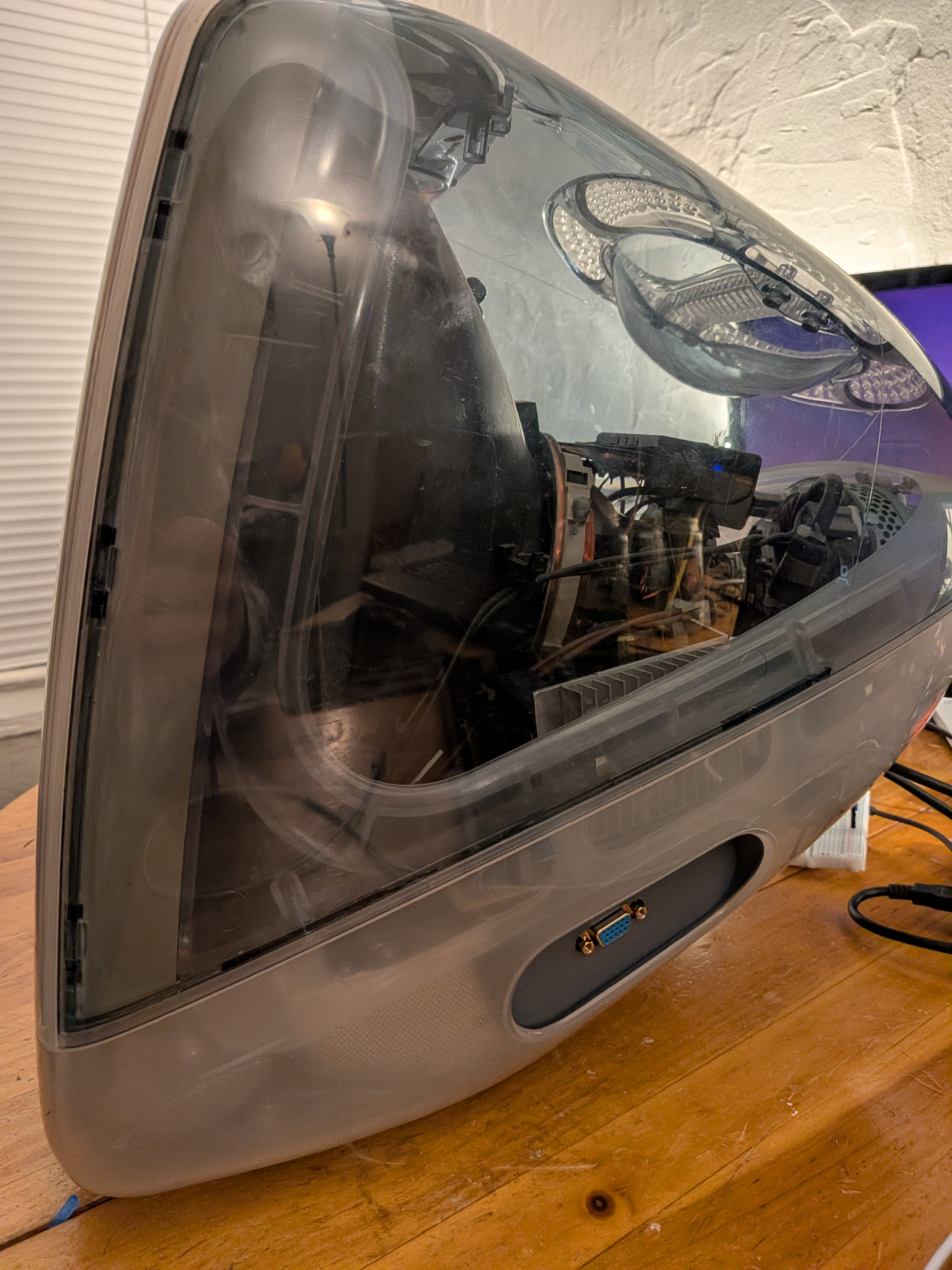
iMac G3 monitor
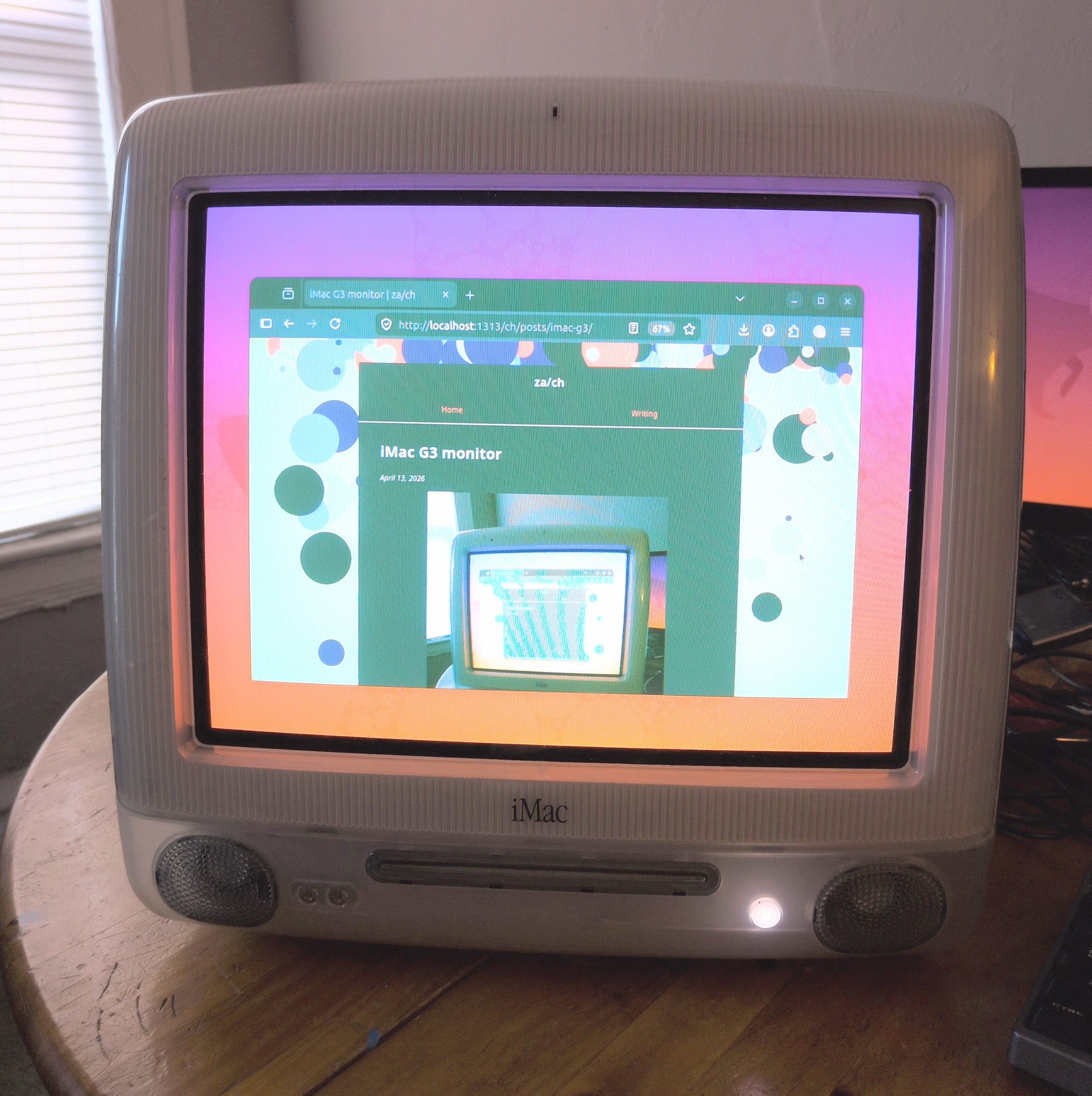
I got this iMac G31 planning to install a flat-panel screen, but never worked up the courage to pull off the cover and expose the possible 30,000 volts across the CRT. Fortunately, there is a less invasive way to mod it!
The reverse engineering project
Rocky Hill and several other people reverse engineered the display inside of the iMac G3, and shared their findings in a Github repo. Because of their efforts, this was a fun little weekend project instead of a months-long slog. Many thanks!
Procurement
OSH Park made the PCBs, and the components were from Digikey. Now that I know a bit more about the setup, I realize that I spent way too much on header pins because I wasn’t sure if they were special in some way. Turns out they were not.
Also, DigiKey accidentally sent a giant Molex D-Sub backshell labeled as a 3.5mm audio jack, so that’s cool? It could come in handy someday.
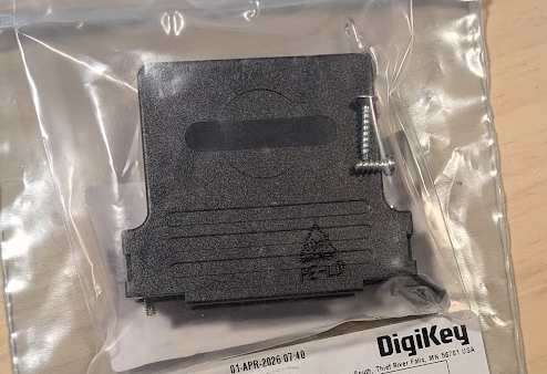
Not a 3.5mm audio jack
Assembly
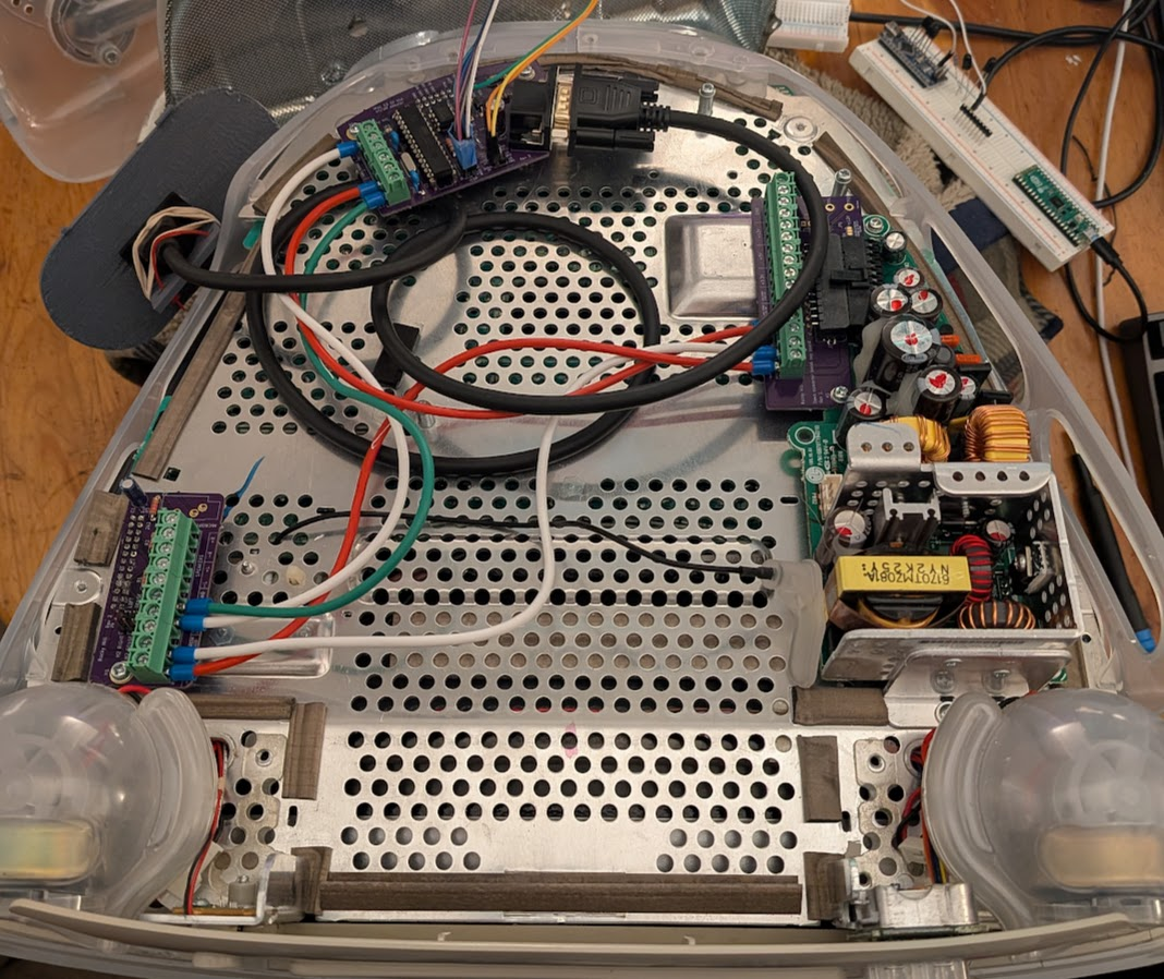
The boards went together pretty easily and fit nicely in the computer.
For the internal wiring, I used some speaker wire that was a prior mis-ship (ordered: 1000 feet of Cat-6 cable, got: 250 feet of speaker wire).
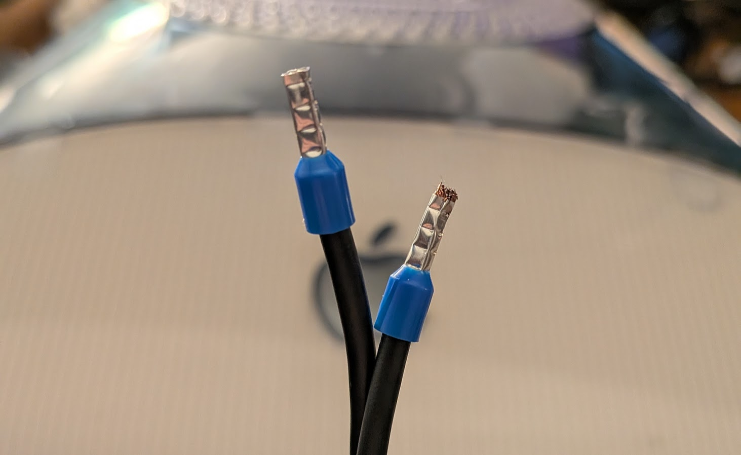
I stuck some ferrules on the ends based on an offhand recommendation in a YouTube video (from Cathode Ray Dude, appropriately enough). He’s right; this made the wires much more pleasant to connect with the screw terminals.
Debugging
After putting it all together, I pressed the power button and got… nothing. No power LED, no image on the screen. Unfortunate.
The power LED was a quick fix. This version of the Mac doesn’t have a green LED; it’s white. It is also not connected to the same pin as the green LED would be. Instead it is attached to the pin labelled “Amber LED” by this project.
After a brief period of despair, I put the original logic board back to make sure the CRT was still generally functional. That worked. So there has to be some signal that can be sent to turn this thing on, and the logic board is sending it.
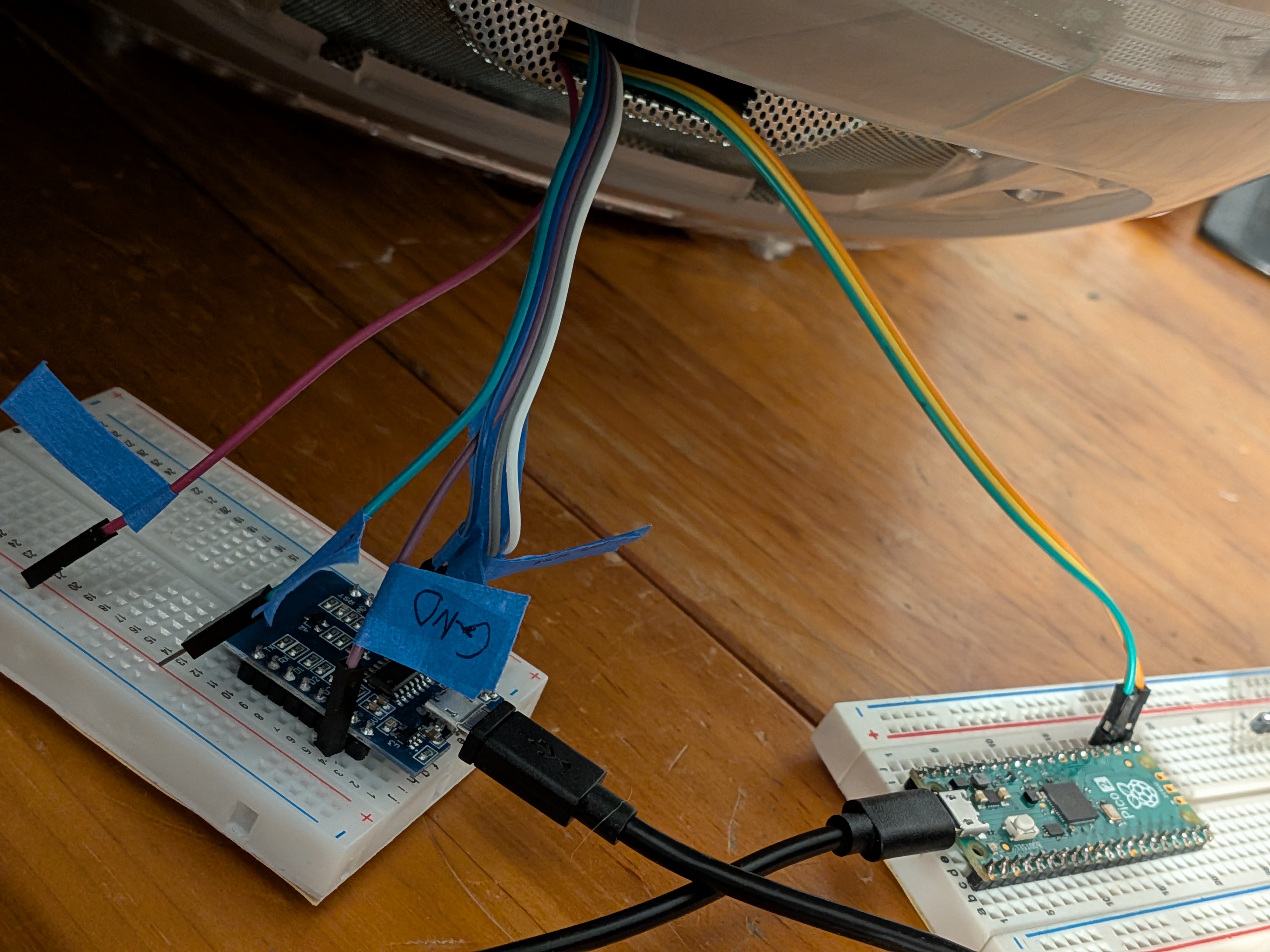
Logic Analyzer Time!
I had never used a logic analyzer, and this was a very positive experience. Sigrok-Pico and PulseView let me sniff the I2C init signals using only parts from around the house.
Logic Analyzers have always seemed mysterious, complicated, and expensive, and this was none of those things. It’s great to know I can throw one together in 5 minutes and get useful information out of it. Signals will know no peace from me.
Tell me your secrets, logic board
I got a recording of the startup sequence from the logic board, and translated that into Arduino code. Still no image.
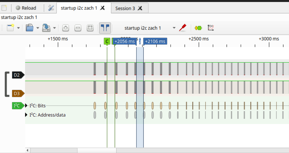
To make sure the arduino was really sending what I’d told it to send, I recorded that with the logic analyzer. Aha! the data was right, but the arduino was sending it a lot faster than the logic board.
I slowed down the clock to 50kHz and added some pauses to match the timing of the signal from the actual logic board. Playing back my recorded init sequence with the new timings… still did not work. (Boo)
Finally, it turned on when I combined the adjusted timings with the initialization sequence already in the arduino sketch (instead of the one I recorded). I didn’t investigate much past this, but my recording must have been incomplete.
Success!
At this point, the major hurdles are clear and it is basically working. It’s time to make it look nice.
Configuration
Initial testing was with a Thinkpad T420’s built-in VGA port. For some reason that computer didn’t understand (or didn’t care) about the EDID information from the monitor, so it didn’t automatically choose the right display settings. I spent a while trying to understand and adjust the Xorg settings to get a 1024x768 @ 75 Hz signal to come out, and pretty much got it there. Eventually I found the text file with modelines ready to go in the repo, and changing the hsync to positive locked it in.
All that was left were some minor adjustments to the monitor’s own settings. I learned later that there is a Java GUI program to tweak these, but I had already done it with a keyboard over the serial connection2 before realizing that.
Final touches
I 3D printed an IO panel to hold the VGA port. Diepzeevogel did the heavy lifting, and I punched out a VGA shape and added some tabs to hold it in place.
There is a VGA-port shaped hole in the iMac where the video output used to be, but that would require part of the bottom cover to be off at all times. That would be fine, I guess but I was planning to print an IO panel anyway to fill the giant hole in the side, so this just made sense.
How-To Guide
I ended up writing a guide for anyone who wants to do this the same way I did. There are so many different options in the original project that it took a while to understand which parts were required for which configuration. Do you need an arduino? A raspberry pi? How much of the computer actually needs to be removed?
Hopefully this helps anyone else who is not sure where to start.
Extra pieces
The logic board seems to work before I pulled it out, so someone on Ebay is probably going to get that.
I also ordered three sets of PCBs and components, and only irreparably damaged one (yay?). So, at some point I will assemble the extra set and send it to an interested party.
-
The first computer my family had was a sage green iMac G3. It was a fantastic machine, which I mostly used to play Pajama Sam. This is a different G3 in a different color, but it has the same charm. ↩︎
-
For a UART bridge, I used the same pico as for the logic analyzer. That pico has been absolutely worth the $5 it cost. ↩︎